Flashing ESPHome Firmware over USB: First Install and Rescuing a Locked Device
ESPHome updates devices wirelessly and in everyday life that's the only thing you need. But there are situations where you can't avoid the cable: the first install onto a blank chip, replacing the bootloader, reading logs from a device that isn't on the network, and above all rescuing a device that won't boot at all after an update.
This article is a reference guide for exactly those cases. We'll look at two very different worlds - a board that has a USB port and only needs a cable, and a device that has no port at all, where you have to dig your way to its serial lines yourself. Then we'll walk through diagnostics, because the serial line is the only place from which a stuck ESP32 can be reliably made to talk.
This isn't an introduction to ESPHome. If you don't have it installed yet, or you're not familiar with the YAML configuration, start with my article ESPHome - A Smart Device from an ESP32 in Minutes. Come back here once you have something to flash.
When you need USB and when OTA is enough
An OTA (wireless) update rewrites only the application partition. Everything else in flash memory stays as it was - and that's exactly where the list of situations OTA can't help you with comes from:
| Situation | Solution |
|---|---|
| First flash onto a new chip | Must be over USB. ESPHome can't reach a device that has never had anything on it - there's nothing to connect to |
| The device isn't on Wi-Fi (wrong password, changed SSID, dead AP) | USB. Wi-Fi credentials are compiled into the firmware, so they can't be fixed any other way than with new firmware |
| The device is locked in safe mode, display black | USB plus erase-flash - covered below |
| You need to replace the bootloader (for example because of an option that requires ESP-IDF v5.1+) | USB. OTA never touches the bootloader |
| You want to read logs or a backtrace from a device that won't connect | USB - see below |
| The device is running and on the network | OTA, straight from the Device Builder. Leave the cable in the drawer |
It sounds counterintuitive, but it's true. ESP-IDF monitors newly flashed firmware after boot, and if the device resets before ESPHome marks it as working, it rolls back to the previous version. A serial flash has no such safety net - it overwrites the application without asking, and when the new version doesn't boot, you have to go back to the device. I describe what that rollback looks like in practice in my post-mortem of one outage.
There is one condition worth knowing about, though: ESPHome ties this rollback to the safe_mode component. If you don't have it in your configuration, ESPHome disables the protection and says so in the log. There's a neat symmetry in that - the very component that can lock a device in safe mode is also what makes OTA safe.
Two cases that differ a great deal
This is the backbone of the whole article. The physical part of the work simply isn't comparable between the two.
A board with a USB port
This covers all the common development boards - ESP32 devkit, ESP32-S3, D1 mini, NodeMCU, Lolin32 and dozens of clones. They carry a USB-to-serial converter (most often a CP2102 or a CH340) or native USB, and that shows up on your computer as a serial port.
What you'll need:
- ✅ A data USB cable - and this is the single most common problem. A cable from a power bank or a charger often carries power only, with no data lines. That looks exactly like a dead board.
- ✅ Nothing else. No adapter, no wires, no soldering.
Often you don't have to press anything at all. Those boards have automatic reset circuitry between the converter and the chip: the serial port's RTS signal is wired to EN (reset) and DTR to GPIO0. esptool (and likewise the web flasher, which has it inside) uses these two signals to put the device into bootloader mode on its own and restarts it after flashing. The esptool documentation documents this wiring in its table of recommended converter-to-ESP connections - EN to RTS, GPIO0 to DTR.
When that isn't enough and you have to reach for the buttons:
- The board has no automatic reset circuitry at all (cheap clones, bare modules on a carrier board)
- You have your own peripheral wired to
GPIO0orENthat overrides the signal - You're getting
Wrong boot mode detected- communication works, but the automatic reset doesn't - You're powering the board from elsewhere and USB carries data only
Entering bootloader mode manually on a board with buttons:
- Hold down the BOOT button (labelled
IO0orFLASHon some boards) - Briefly press and release RESET (or
EN) - Release BOOT
- Start the flash
The esptool documentation puts it plainly: "The ESP32 will enter the serial bootloader when GPIO0 is held low on reset. Otherwise it will run the program in flash." The BOOT button does nothing more than pull GPIO0 to ground. GPIO2 must also be left unconnected or held low - on ready-made boards that's always satisfied, but watch out for it on your own PCBs.
Newer chips have a USB controller built in and the board may have two USB ports - one routed through the converter (UART) and one straight into the chip. That second one comes in two different flavours, though, and they're worth keeping apart, because they behave in opposite ways:
- USB-OTG (ESP32-S2 and S3) is a configurable controller, so it only presents itself as a serial port when the firmware enables it. If the device disappears from your list of ports after flashing, it isn't broken - the new configuration simply didn't turn USB CDC on.
- USB-Serial-JTAG (ESP32-C3, and alongside OTG on the S3) is fixed hardware. It exists regardless of what's in flash, so you can flash through it even on a device with empty or broken firmware.
The port labelled UART is still the safe bet for flashing - Espressif lists it as the default in the user guides for its own boards. If the board doesn't have one, the native port works too, but you'll occasionally have to put it into bootloader mode with the buttons.
A device with no USB port
This covers finished commercial devices - Sonoff NSPanel, Shelly, Sonoff Basic, bulbs, sockets. Inside they have an ESP32 or an ESP8266, but the manufacturer didn't break it out anywhere, because nobody expected anyone would ever change the firmware.
What you'll need:
- ✅ A USB-TTL adapter with a CP2102 or CH340 chip
- ✅ Jumper wires, Female-to-Female, at least five
- ✅ A screwdriver to open the device
- ⚠️ The adapter switched to 3.3 V, if it has a switch
- ⚠️ Sometimes a soldering iron, when the device has no header broken out
- ⚠️ On mains-powered devices, power disconnected
CP2102 USB 2.0 to TTL UART Module
 USB
USB
Dupont cables 10cm / 20cm / 30cm - male / female
The RX and TX data pins must be on 3.3 V logic. An adapter switched to 5 V won't destroy your chip every single time, but it will destroy it often enough - and it's irreversible. The ESPHome documentation is categorical: "You MUST make sure the data (RX and TX) and VCC pins are set for 3.3V."
On mains-powered devices you should also disconnect 230 V before any handling. We're working with 3.3 V logic, but there are parts on the board that have nothing to do with it.
The wiring is always the same four connections, just named differently:
| Device | USB-TTL adapter | Note |
|---|---|---|
TX | RX | Crossed over! |
RX | TX | Crossed over! |
GND | GND | Nothing works without a common ground |
5V, if the device has one | +5V | The device steps 5 V down with its own regulator. See the warning below |
3V3, when there is no 5V pin | 3V3 | Never put +5V on a 3V3 pin - that destroys the chip. Expect the adapter's regulator to fall short, and have an external 3.3 V supply ready |

And here's what that header actually looks like, on the NSPanel as an example:
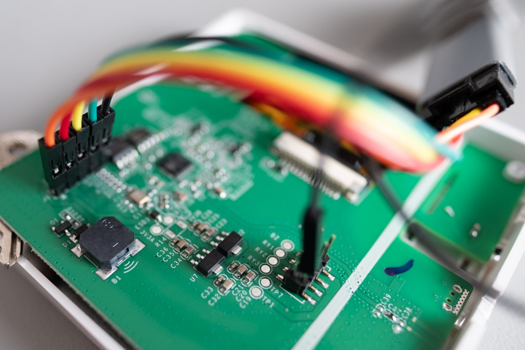
+5V, not the converter's 3V3 pinThis is the trap that produces a perfectly convincing but completely wrong diagnosis. The 3V3 pin on a USB-TTL adapter is fed by a tiny regulator on its board that delivers roughly 50–100 mA. That's plenty for the flash itself - the firmware writes fine and everything looks good. But at boot Wi-Fi asks for many times that, the supply collapses and the device restarts. You then see rst:0x1 in the log and start hunting for a bug in firmware that is perfectly fine. I break it down below.
Use the converter's +5V pin, which comes practically straight from USB VBUS. The device converts those 5 V with its own regulator, which is rated for it. An external supply usually isn't needed, though a port limited to 500 mA can be tight - a USB 3.0 port helps.
Entering bootloader mode manually is mandatory here, because there's no automatic reset circuitry on the board:
- Disconnect the device from all power
- Connect the
GPIO0pin (often labelledIO0) toGND- with a wire, a jumper, or simply hold it there - Apply power (plug the adapter into your computer's USB)
- Wait a few seconds, then you can remove the short
- You'll know it worked when the flashing tool connects to the device
The order matters here: GPIO0 has to be at ground at the moment the chip starts. Connecting it afterwards has no effect whatsoever.
A device connected to 230 V and at the same time to a USB-TTL adapter in your computer is the combination that costs you the adapter, the USB port, or more. One at a time, always.
The specific procedure for the Sonoff NSPanel - how to open it, where the header is and what each pin does - is in my separate NSPanel article.
Three ways to get firmware into the device
Once the device is physically connected and in bootloader mode, all that's left is picking a tool. All three use esptool under the hood, so the result is identical - they differ in convenience and in what they can do.
| Method | When to use it |
|---|---|
| Device Builder → Install → Plug into this computer | The standard choice when you have ESPHome in Home Assistant. Nothing to download |
| web.esphome.io standalone | You don't have ESPHome in HA, you're flashing from someone else's computer, or you already have the .factory.bin and just want to write it |
esptool from the command line | When you need erase-flash, specific addresses, a different baud rate, or you want to script it |
Device Builder: Plug into this computer
The Install dialog now recognises on its own that the device has never been flashed and tells you so:
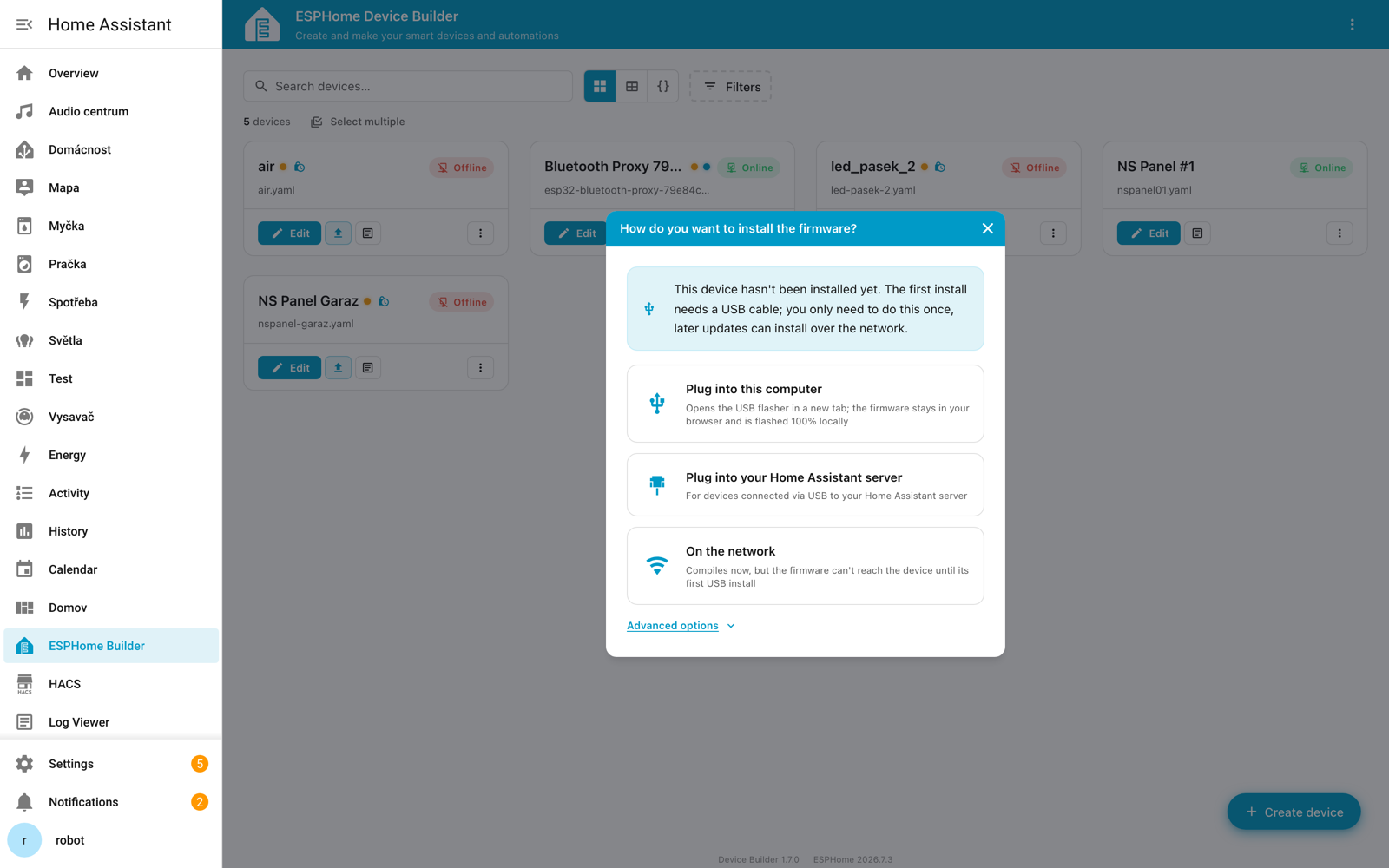
It gives you three obvious options, plus a fourth tucked away under Advanced options:
| Option | What it does |
|---|---|
| Plug into this computer | The ESP is in this computer's USB. A web flasher opens in a new tab, the firmware stays in the browser and the flash happens 100% locally |
| Plug into your Home Assistant server | The ESP is in a USB port on the Home Assistant server. Useful when your HA runs on a Raspberry Pi within arm's reach |
| On the network | Compiles the firmware, but it can't be uploaded until the first USB install |
| Download firmware binary | Compile here and download the binary, then flash it manually with your preferred tool. Compiles and offers the file for download to disk. This is the option you want when you're going to flash via web.esphome.io, esptool, or from an entirely different computer |
Download firmware binary is hidden under Advanced optionsYou can't see it in the screenshot above, and that isn't a mistake - the dialog tucks it under the Advanced options disclosure at the bottom. Expanding it reveals two entries:
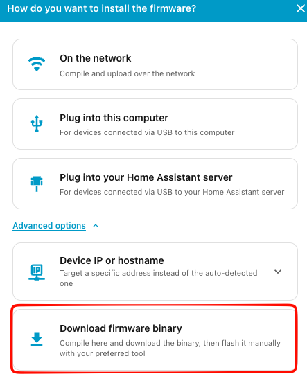
- Device IP or hostname - install to a specific address instead of the auto-detected one
- Download firmware binary - this is the one you're looking for
Note the wording "Compile here". The compile runs wherever Device Builder runs - typically on the server with Home Assistant, not on the computer you download the file to. Downloading alone therefore doesn't speed anything up, it only moves the file elsewhere; more on that below.
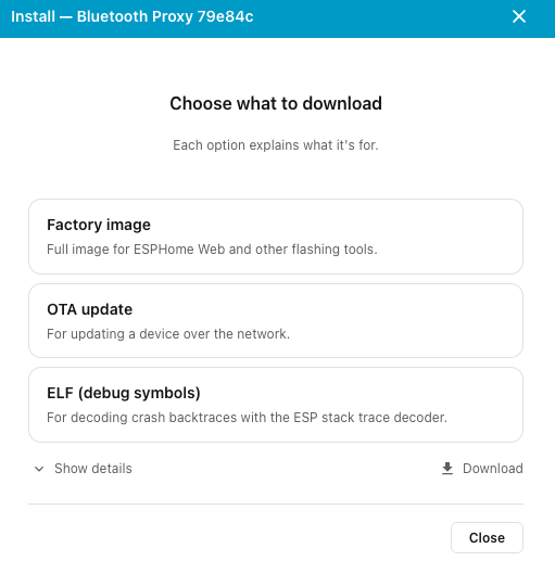
Factory image, not OTA updateAfter clicking Download firmware binary, ESPHome compiles first and then asks "Choose what to download". There are three entries - pick one and confirm with the Download button:
| Option in the dialog | Downloaded file | What it's for |
|---|---|---|
| Factory image | <name>-firmware.factory.bin | Full image for ESPHome Web and other flashing tools. This is what you want for a serial flash |
| OTA update | <name>-firmware.ota.bin | For updating a device over the network. Wireless updates only |
| ELF (debug symbols) | an .elf file | For decoding crash backtraces with the ESP stack trace decoder. Not firmware - useful when you're deciphering a crash, see below |
The difference between the first two matters. OTA update is the application only - flashed over serial to address 0x0 it won't boot, because the bootloader and the partition table are missing. Factory image is a merged image of everything needed, starting from address zero. For a first install and after every erase-flash you must have the factory image; nothing else will come up.
Older guides and the help text inside web.esphome.io itself call these Modern Format and Manual Download - the interface has been renamed since, but it's the same thing.
web.esphome.io standalone
The same tool, just without Home Assistant around it. Handy for rescues and for situations where you have no ESPHome installed anywhere.
- Open web.esphome.io in Chrome or Edge
- Connect → pick your serial port in the browser dialog
- An ESP Device card appears with a Connected badge and a row of actions
- Click the upload icon (second in the row) → the dialog "Install your existing ESPHome project" opens with a file picker
- Select the downloaded
.factory.binand confirm with Install - Let it upload; on an ESP32 that takes about a minute
Step 4 deserves attention: web.esphome.io flashes from a file on your disk, not from some connected ESPHome. It doesn't need to see your Home Assistant, doesn't need to be on the same network as it, and doesn't need to know anything at all about your installation. All it needs is the binary and a device on USB. ESPHome spells this out in that very dialog, which includes instructions for obtaining the file: Open your ESPHome Device Builder → device card menu → Install → Manual Download → Modern Format.
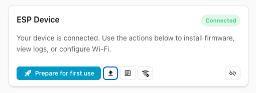
This is the trickiest part of that interface. Prepare for first use is the only action with a text label, and it's highlighted in blue on top of that, so your hand goes there on its own. Yet it's the one you don't want: it flashes generic ESPHome firmware meant for later adoption, not your binary.
The action you're looking for is the upload icon right next to it - with no label. The other two icons are logs and Wi-Fi settings, and disconnect is on the right. Hover over them for a moment and a tooltip appears.
Web flashers are built on the Web Serial API, and that has two conditions that are easy to trip over:
- It doesn't work in every browser - the reliable ones are Chromium-based (Chrome, Edge, Opera, Brave), and as of Firefox 151 it works there too. Not in Safari, not even on iOS. MDN lists it under limited availability precisely because "it does not work in some of the most widely-used browsers".
- It requires a secure context - that is,
https://orlocalhost. Quoting MDN: "This feature is available only in secure contexts (HTTPS), in some or all supporting browsers."
And here's the recurring trap: if you reach Home Assistant over http://192.168.1.x:8123, the Plug into this computer option will not work for you. It isn't a bug in ESPHome or on your computer - the browser simply refuses access to a serial port from an insecure page. You have three ways out: use the option with the server's USB port, put Home Assistant behind HTTPS (I have an article on a Let's Encrypt certificate for that), or download the .factory.bin and flash it through web.esphome.io, which runs on HTTPS.
esptool from the command line
esptool is Espressif's official tool and the only one of the three paths that gives you full control. You install it with pip install esptool; if you have ESPHome installed locally, you already have it.
A basic flash:
esptool --port /dev/cu.usbserial-0001 --baud 460800 \
  write-flash 0x0 my-firmware.factory.bin
Wiping flash memory completely - this is the thing no web flasher can do:
esptool --port /dev/cu.usbserial-0001 erase-flash
Reading a chunk of flash into a file, for example when you want to salvage older firmware from the second OTA slot:
esptool --port /dev/cu.usbserial-0001 read-flash 0x1d0000 0x200 app1.bin
esptool moved to dashes in its fifth generation: write-flash, erase-flash, read-flash, merge-bin. Older installations used esptool.py with underscores (write_flash, erase_flash). If a command from this article reports an unknown parameter, you have an older version - underscores will help. You don't need to pass --chip; the documentation says "esptool will detect the type of chip when it connects to the serial port."
ESPHome also has its own commands for serial work that are worth knowing, because they handle the compile for you:
# compile, flash over USB and open the logs straight away
esphome run my-device.yaml --device /dev/cu.usbserial-0001

# just upload the last build
esphome upload my-device.yaml --device /dev/cu.usbserial-0001

# just watch the log over serial
esphome logs my-device.yaml --device /dev/cu.usbserial-0001
According to the CLI documentation, the --device parameter exists to "manually specify the port/IP to use for upload and logging" - it accepts both a serial port and an IP address for OTA.
Drivers and port names per operating system
The most common report I hear about flashing is "the port isn't in the list". In nine cases out of ten it's the driver or the cable, not the device.
| System | What the port is called | What to watch out for |
|---|---|---|
| Windows | COM3, COM4... (find it in Device Manager) | Windows often offers a generic driver that doesn't work. Install the chip vendor's one |
| macOS | /dev/cu.usbserial-0001, /dev/cu.SLAB_USBtoUART, /dev/cu.wchusbserial* | Always cu., never tty. - see below |
| Linux | /dev/ttyUSB0 (CP2102, CH340), /dev/ttyACM0 (native USB) | Your user has to be in the dialout group |
Drivers by the chip on the adapter. The ESPHome documentation treats all three the same way: depending on the chip and your operating system, a driver may need installing, so check that before you go hunting for the fault elsewhere.
- CP2102 / CP2104 (Silicon Labs) - CP210x USB to UART Bridge VCP Driver. The
cp210xdriver has been part of the Linux kernel for a long time; on Windows you usually do have to add it - CH340 / CH341 (WCH) - the CH34x driver. In my experience this is the one most often missing
- PL2303 (Prolific) - the PL2303 driver. Clones are repeatedly reported to have trouble with newer official drivers, so where you have the choice, reach for a CP2102 or CH340 instead
cu. yes, tty. noOn macOS every serial port appears twice - as /dev/tty.something and /dev/cu.something. The difference is that the tty. variant can wait for the DCD signal on open, and nobody asserts that on a USB-TTL adapter. esptool then simply hangs with no error message while you go looking for a wiring problem. Use cu.
You can list the current ports like this:
ls /dev/cu.*
Without permission on the port you'll get Permission denied, or you won't see the port at all. The esptool documentation recommends adding your account to the dialout group (uucp on some distributions):
sudo usermod -aG dialout $USER
After adding yourself you have to log out and back in, otherwise the change won't take effect.
And one special case: if ESPHome runs in a Docker container, you have to pass the port through with --device /dev/ttyUSB0, or it won't find it inside.
Compiling and flashing from another machine
Compilation is by far the most demanding thing in the whole ESPHome workflow, and it happens wherever Device Builder runs - typically on the very same server that hosts Home Assistant. On a Raspberry Pi, a Home Assistant Green or a NAS, that means minutes of waiting per device.
The good news is that something can be done about it, and it isn't a workaround: Device Builder can offload the compile over the network to a more powerful machine, while the configuration stays only in Home Assistant. Because that's a topic of its own - pairing, version matching and network traps - I've given it its own article.
Why compiling is so slow, how much it actually speeds things up, how to pair two Device Builders, and when it doesn't work, I cover in ESPHome Compiles for Minutes? Offload the Build to a Faster Machine.
The rest of this section is about two related things that solve a different problem - how the firmware gets into a device that isn't next to the server, and what to do when you can't use the ESPHome desktop app.
Downloading the image and flashing from another computer
Once the firmware is compiled, it still has to get into the device. And here comes the second separation: you can download the image as a file and flash it from anywhere. The click-by-click procedure, and why you want Factory image rather than OTA update, is covered above - all that matters here is that you end up with a single file on disk.
And that file is a portable artefact. It doesn't matter whether the device is plugged into the machine running Home Assistant, whether it's even on the same network, or whether that computer knows anything about your installation. All it needs is the binary and a device on a cable. So you can flash from the Mac on your desk, from the laptop you carried over to the panel in the hallway, or from a colleague's computer.
For devices with no USB port this is often the only practical route. You simply can't carry a disassembled NSPanel with a USB-TTL adapter down to the server in the basement.
Let's be honest about this, because it's easy to fool yourself. Download firmware binary separates where the device is from where the configuration is. It doesn't separate where it compiles.
So if you click Install and don't have remote build paired, compilation runs on whichever machine Device Builder lives on - that weak server. The button is in a browser on your fast Mac, but the computation is on the NAS and you wait out your minutes. The two complement each other: remote build solves speed, downloading the image solves reach.
Alternative: full ESPHome on the fast machine
Remote build needs Device Builder on both ends, so there are cases where you can't use it - a headless Linux server, a platform without the desktop app, or simply preferring to work in a terminal. Then the way forward is a full ESPHome installation on the fast machine, working there directly.
Treat this as an alternative, not a recommendation. It hands you back the two-copies-of-the-configuration problem that remote build eliminates.
One thing for peace of mind: ESPHome on that other machine doesn't replace the one in Home Assistant, it's just a compiler. The devices still belong to the ESPHome integration in Home Assistant and the entities stay where they were.
How to get it running. Two routes that don't need the desktop app:
Docker is a single command, which the documentation gives as:
docker run --rm --net=host -v "${PWD}":/config -it ghcr.io/esphome/esphome
You'll find the interface at http://localhost:6052. The --net=host flag is there for mDNS - without it the container won't find devices on your network. On Docker Desktop (macOS, Windows) --net=host doesn't work; replace it with -p 6052:6052. The directory you run the command from becomes the configuration directory.
pip requires Python 3.12 or newer, and the documentation recommends installing it into a virtual environment:
# command line only
pip install esphome

# command line plus the Device Builder web interface
pip install "esphome-device-builder[esphome]"
esphome dashboard no longer existsThe CLI documentation states it flatly: "the built-in dashboard command has been removed". So pip install esphome gives you the command line and nothing else - and with it no remote build, because that's a Device Builder feature, not a CLI one. If you want the interface, you need the desktop app, the Docker image, or the esphome-device-builder package.
And a note for honesty's sake: the documentation today lists only pip for manual installation. You won't find pipx or uv in it. They'd probably work, but it isn't the officially supported route, so I won't recommend them here.
How to get the configurations there. This is the tedious part, because as soon as you have ESPHome in two places you have two copies of your configurations - and nothing will tell you which one is correct.
| Option | How it works | Weakness |
|---|---|---|
Network share of /config/esphome | Mount the Home Assistant directory on the fast machine over Samba and work in it directly | One source of truth, no synchronisation. But building over a network drive is slower and you also share the .esphome directory - see the trap below |
| Git repository | Configurations in git, both instances pull from it | You have to remember to commit and pull. But you get history |
| Editing primarily on the fast machine | You write and compile only here | Simplest to reason about, but with the machine off you have no way to flash |
Before you sit down with git, know that Device Builder already keeps its own git-backed version history. Per the README it commits every YAML change in the configuration directory "whether the edit came from the dashboard, an external editor, a script, or an AI agent working in the directory", can diff and restore them, and never commits secrets.yaml. If the directory is already a git repository, it adopts it rather than reinitialising, and never modifies your .gitignore.
If you maintain the repository yourself and don't want somebody else's commits in it, turn it off under Settings → Expert mode → Save version history.
secrets.yaml into your own repositoryIt holds your Wi-Fi password, the API encryption key and the OTA password. It doesn't belong in a repository even a private one - getting it back out of git history afterwards is deeply unpleasant.
# .gitignore
secrets.yaml
.esphome/
Keep a secrets.yaml.example alongside it instead, with the same keys but empty values. Commit that one freely - it documents what the configuration needs, and when setting up a new machine you just copy it and fill it in.
With a Samba share you don't have this problem, because secrets.yaml is shared automatically. That's an advantage and a risk at the same time.
The build itself. With the configuration in place, compiling is one command:
esphome compile nspanel-livingroom.yaml
The CLI documentation says exactly what you'd expect - "validates the configuration and compiles the firmware", so it uploads nothing anywhere. You'll find the result in the .esphome directory, which ESPHome creates next to your configuration. The exact path depends on the toolchain:
| Toolchain | Firmware (for OTA) | Factory image (for USB) |
|---|---|---|
| Native ESP-IDF (default since 2026.7) | .esphome/build/<name>/build/<name>.bin | .esphome/build/<name>/build/firmware.factory.bin |
PlatformIO (--toolchain platformio) | .esphome/build/<name>/.pioenvs/<name>/firmware.bin | firmware.factory.bin in the same directory |
That firmware.factory.bin is precisely the file you want for a serial flash - I explain why above. Flash it per esptool or through web.esphome.io. Or, more conveniently, let ESPHome do the flashing:
# OTA over the network - the device is already flashed and running
esphome upload nspanel-livingroom.yaml

# over USB - first install or a rescue
esphome run nspanel-livingroom.yaml --device /dev/cu.usbserial-0001

# just watch the log, over the network or over serial
esphome logs nspanel-livingroom.yaml --device /dev/cu.usbserial-0001
The difference between upload and run is that upload per the documentation "uploads the most recent firmware build" - it flashes what's already compiled - whereas run compiles, flashes and immediately opens the logs. After esphome compile, upload is all you need.
For bulk updates the CLI has esphome update-all, which per the documentation "compiles and uploads firmware to all devices via OTA". On a fast machine this is a completely different experience from a weak server, where compiling ten devices stretches into a whole afternoon.
What to watch out for
ESPHome versions don't have to match across two machines. On a mismatch ESPHome cleans the build directory itself, so all you lose is the incremental build. What exactly happens, and how to enforce a version match for remote builds, is covered in the remote build article.
Flashing is a different discipline from compiling. ESPHome older than 2025.10 that authenticates with a password cannot get firmware into a device already running 2026.1 or later. I cover it in the ESPHome article, and it applies to precisely this scenario: all it takes is last year's version frozen on that second machine and flashing stops working without you understanding why. Keep both instances updated.
The toolchain on that fast machine will eat gigabytes. The ESP-IDF cache directory on my Mac grew to just under 5 GB, and that's entirely normal - it holds the complete compiler for both Xtensa and RISC-V. If you don't watch for it on a small SSD, it arrives as an unwelcome surprise. Two commands clean up: esphome clean removes that device's build files, whereas esphome clean-all per the documentation "cleans all build files, PlatformIO platform and package files, and the PlatformIO core directory" - including the toolchain, which then has to be downloaded again. On the fast machine leave it alone; on a weak server with a small disk it's the first place to look for free space.
Don't share .esphome between machines running different versions. This is the trap with the Samba option specifically: two machines with different ESPHome versions hammering one build directory will keep knocking out each other's cache. Every build there will be a full one, because the other machine cleaned the directory in the meantime. Either keep the versions the same, or separate the build directories with the ESPHOME_BUILD_PATH and ESPHOME_DATA_DIR variables. With remote build you don't have this problem - each side has its own.
The host architecture doesn't matter. ESPHome always cross-compiles - the target is Xtensa or RISC-V, something entirely different from the processor the build runs on. That Apple Silicon is a fully capable build machine is evident from ESPHome shipping a separate native package for it (arm64). So you don't need to hunt for emulation, nor worry that an ARM Mac will produce different firmware from an x86 server.
Rescue and diagnostics
This is where the part this article exists for begins. What the following four situations have in common is that they look like dead hardware but aren't - and all of them can only be fixed over the serial line.
Locked safe mode: the factory.bin won't overwrite it
Symptoms: the device won't come up after an update, the display stays black, it never appears on Wi-Fi. You reflash it and nothing changes. You reflash again and it's still the same.
The serial log then shows this:
[C][safe_mode:189]: Unsuccessful boot attempts: 10
[E][safe_mode:201]: Boot loop detected
The device has latched into safe mode. That's an ESPHome protective feature: after ten failed boot attempts it boots minimal firmware without your configuration, so that flashing over OTA remains possible. A black screen is entirely expected in that state - safe mode never starts the display at all.
And now the insidious part, in two layers.
The failed-boot counter survives a power cycle. The default safe_mode setting on the ESP32 is storage: flash, and the ESPHome documentation notes that the counter is stored in flash and a power loss does not clear it - at the cost of a small amount of flash wear on each boot. So every power cycle you try in order to revive the device is useless; the counter stays at ten.
And the factory.bin doesn't clear it. This needs explaining, because the name "factory image" suggests the opposite. Look at how ESPHome lays out 4 MB of flash for ESP-IDF:
| Partition | Address | Size | In the factory.bin? |
|---|---|---|---|
| bootloader | 0x0 | 32 kB | ✅ yes |
| partition table | 0x8000 | 4 kB | ✅ yes |
otadata | 0x9000 | 8 kB | ✅ yes |
phy_init | 0xb000 | 4 kB | – |
app0 (application) | 0x10000 | 1,792 kB | ✅ yes |
app1 (second OTA slot) | 0x1d0000 | 1,792 kB | – |
nvs (the counter lives here) | 0x390000 | 448 kB | ❌ no |
See it? ESPHome puts the nvs partition at the end of flash memory, behind both application slots. The factory.bin is a merged image of the bootloader, the partition table, otadata and the application - that is, things from zero up to just under 2 MB. It never reaches 0x390000. You can reflash the device as many times as you like and the counter will still be sitting there.
The fix is to erase the whole flash and only then write the firmware:
# erase the ENTIRE flash including NVS - this is the essential step
esptool --port /dev/cu.usbserial-0001 erase-flash

# and only then flash the firmware
esptool --port /dev/cu.usbserial-0001 --baud 460800 \
  write-flash 0x0 my-firmware.factory.bin
Wi-Fi credentials are compiled into the firmware, so erasing NVS loses you nothing important. You only lose things stored at runtime - globals with restore_value: true and similar small stuff.
Put this into the configuration of every device you don't want to crawl to with a cable:
safe_mode:
  storage: rtc
The counter moves into RTC memory, of which the documentation says it survives "software reboots (restarts, OTA updates, crashes) and deep sleep but not power loss." That's exactly what you want: safe mode stays as a safety net for software crashes, but a locked device is revived by an ordinary power cycle instead of a serial line.
As a bonus it cuts down flash writes, because the counter no longer increments in flash on every boot. storage: rtc is available on all platforms with RTC memory; it isn't available on the RP2040, ESP32-C2 and ESP32-C61.
The full account of how I arrived at that diagnosis, and how many blind alleys I went down on the way, is in my article When the NSPanel won't boot after an update.
A boot loop with rst:0x1: insufficient power
Symptoms: the flash completes without error, but the device then restarts roughly every second. The log repeats:
rst:0x1 (POWERON_RESET),boot:0x13 (SPI_FAST_FLASH_BOOT)
That code is the whole diagnosis. rst:0x1 (POWERON_RESET) means the chip actually lost power - software didn't crash, the volts simply went away. If the firmware were crashing, you'd see rst:0xc (SW_CPU_RESET) along with a Guru Meditation Error and a backtrace.
The most common cause is powering the device from the 3V3 pin on the USB-TTL converter, as described above: the regulator on the converter board delivers 50–100 mA, flashing fits into that, but Wi-Fi starting up asks for many times more and the supply collapses.
What to do about it:
- Move the power lead to the converter's
+5Vpin - it comes practically from USB VBUS and the device converts it with its own regulator - If that doesn't help, try a USB 3.0 port instead of 2.0; it gives you a higher current limit
- On hungrier devices use an external supply and take only
RX,TXandGNDfrom the converter - Check that you have only one common ground - two supplies without a shared GND can produce exactly the same symptoms
What makes the trap nasty isn't that it's easy to overlook, but that the data looks trustworthy. You sit over a serial log that faithfully documents the limits of your adapter, and you use it to hunt for a firmware bug that isn't there. I lost several hours that way myself - in detail in the post-mortem. Before you start trusting data, verify the rig you measured it on.
The bootloader: OTA never changes it
This case is rare, but when you hit it, it's unpleasant.
An OTA update rewrites only the application partition. The bootloader, which lives at address 0x0, remains the one that got into the device during the first serial flash - possibly two years ago, with the ESP-IDF version of the day.
The practical consequence: some advanced ESP-IDF options require a bootloader from a specific framework version or newer. When you enable such an option and push it over OTA, the compile passes, the upload passes, and the device won't boot at all - because the old bootloader can't load the new image. And because it won't boot, you can't rescue it with another OTA. All that's left is a serial reflash, which finally rewrites the bootloader as well.
Especially when the device is somewhere you can't reach with a cable. The procedure that sidesteps this problem: first reflash the device once over serial with the current ESPHome version (which gets you a current bootloader too), and only then enable the option and send it over OTA. Doing it the other way round can take the device off the wall for you.
Reading logs and backtraces over the serial line
When the device isn't on the network, esphome logs over OTA won't help you and neither will the web interface. The serial line is the only way to learn what's going on.
You have three ways to get at the log:
# 1. The ESPHome CLI - the best option, it decodes component names too
esphome logs my-device.yaml --device /dev/cu.usbserial-0001

# 2. Any serial monitor, when you don't have the configuration to hand
screen /dev/cu.usbserial-0001 115200
# to quit: Ctrl+A, then K, then Y
The third option is reading the log right inside web.esphome.io - connect with Connect and click the log icon on the ESP Device card (third in the row, unlabelled - see above). It's the quickest route when you just want to see what the device is saying and have nothing installed.
In bootloader mode the chip prints no log at all; it's waiting for flasher commands. So to read the log, leave GPIO0 alone and let the device boot normally.
What to look for in the log. The serial log has the advantage of showing you what happens before ESPHome even starts. The first lines come straight from the ROM bootloader:
| Line in the log | What it means |
|---|---|
rst:0x1 (POWERON_RESET) | Loss of power - see the boot loop above |
rst:0xc (SW_CPU_RESET) | A software reset, usually after a firmware crash |
rst:0x10 (RTCWDT_RTC_RESET) | A stuck watchdog |
Guru Meditation Error | A firmware crash; the backtrace is right underneath |
waiting for download | The chip is in bootloader mode, GPIO0 is still at ground |
invalid header: 0xffffffff | There's no valid application in flash - an unfinished flash, or you wrote a plain .bin instead of a .factory.bin |
Unsuccessful boot attempts: 10 | Locked safe mode - see above |
The backtrace itself is a row of hexadecimal addresses and is unreadable without decoding. How to turn it into line numbers is described in the section Backtrace without a serial cable - you need the machine you compiled the firmware on.
Troubleshooting
A quick overview of messages and what usually lies behind them.
The port doesn't show up in the list
Work through this in order; it's roughly by likelihood:
- Swap the cable. Seriously. The ESPHome documentation stresses it too: "a power only USB cable that usually comes presupplied with powerbanks won't work." You need a data cable
- Install the driver for the chip on your adapter - see the table above
- Try a different USB port, ideally directly on the computer rather than through a hub
- On macOS, check you're looking at
/dev/cu.*and nottty. - On Linux, check the
dialoutgroup - Try a different adapter - CP2102 and CH340 clones of varying quality do varying things
Failed to connect to ESP32 or Wrong boot mode detected
This message is actually good news: communication works, the chip just didn't switch into bootloader mode.
- On devices with no USB port, check that
GPIO0was atGNDbefore power was applied, not afterwards - On a board with buttons, use the manual procedure: hold BOOT, tap RESET, release BOOT
- Check that no other program is holding the port - a serial monitor left open, or a running
esphome logs, is the classic. The esptool documentation warns about it explicitly - Sometimes lowering the baud rate helps
The flash starts and dies halfway through
The esptool documentation is unambiguous here: "If flashing fails with random errors part way through, retry with a lower baud rate."
esptool --port /dev/cu.usbserial-0001 --baud 115200 \
  write-flash 0x0 my-firmware.factory.bin
The documented default is 115200, and esptool drops to that speed for the initial handshake anyway - higher rates are only used for the data transfer itself. I work downwards through 460800 → 115200 → 57600, but that's my practical experience rather than a documented recommendation: 460800 works on a good adapter with short wires, while with long jumper leads or a cheap CH340 clone it tends to be marginal. If you need to rule speed out as the cause entirely, the documentation suggests trying -b 9600 once - it's slow as a mill, but it answers the question.
Invalid head of packet or a corrupted log
This is almost always hardware:
- A bad cable - esptool lists it as a typical cause ("Using bad quality USB cable")
- TX and RX crossed the wrong way. The ESPHome documentation mentions this as a routine thing: "RX and TX can be sometimes swapped." If you're not sure, just try swapping them - you won't damage anything
- A missing common GND. Without it the serial signal has no defined reference and you read random bytes. It happens most often when you power the device from an external supply and forget to tie GND to the adapter
- A short against metal parts inside the device - on the NSPanel the display's metal shield sits right next to the header
- Long or thin jumper wires
The firmware flashes, but the device doesn't reach Home Assistant
So the flash wasn't the problem. Look in the serial log to see whether the device joined Wi-Fi at all. If you see No networks found and you have a hidden SSID, the documented fix is hidden: true - note that it belongs on the entry inside networks:, not in the top-level wifi:. When a package won't let you set it (typically with NSPanel Easy), wifi: fast_connect: true helps instead: it skips the scan and connects straight to the first configured network - I explain why over at the NSPanel article. The rest of the diagnostics, including the case where the device is on Wi-Fi and still doesn't appear, is in the Troubleshooting section of the ESPHome article.
I flashed a .bin instead of a .factory.bin
You haven't destroyed anything; the device just has no valid image and reports invalid header in the log. Download the right file and flash again - no erase-flash needed.
Evaluation
Serial flashing has a reputation as unpleasant work and partly deserves it: on a device with no USB port you're digging around in plastics, holding wires in place and watching out for shorts. But it's the only safety net that always works. OTA is more convenient, faster and in ninety-nine cases out of a hundred the only thing you need - but in the remaining one, only the cable will save you.
What I'd take away from this as a reader:
- ✅ Keep a USB-TTL adapter at home, even if you don't use it for years
- ✅ Power from
+5V, not the converter's3V3 - ✅
safe_mode: storage: rtcin every configuration - ✅ A data cable, not the one from your power bank
- ❌ Don't trust the
factory.binto erase everything - ❌ Don't blindly enable options wanting a new bootloader over OTA
- ❌ Don't hunt for firmware bugs until you've verified the power supply
- ❌ Don't put 5 V on the data pins
And one thing I wish I'd known sooner: remote build. For years I waited on compiles on a weak server, assuming nothing could be done about it, while ESPHome could do it all along - the configuration stays in one place and a machine that's up to the job does the computing. If your Home Assistant runs on a Raspberry Pi or a NAS, start here.
That single line, safe_mode: storage: rtc, is then the best investment in the whole article. Writing it takes five seconds, and on the day your device won't come up it saves you an entire afternoon with a screwdriver.
Related Articles
- ESPHome - A Smart Device from an ESP32 in Minutes
- ESPHome Compiles for Minutes? Offload the Build to a Faster Machine
- Sonoff NSPanel with NSPanel Easy - ESPHome install, pinout and troubleshooting
- When the NSPanel won't boot after an update - memory and safe mode diagnostics
- From NSPanel_HA_Blueprint to NSPanel Easy - migrating over OTA without taking the panel off the wall
- SSL certificate for Home Assistant (Let's Encrypt)
Sources
- ESPHome: Physical Device Connection - the official overview of connection methods, drivers and entering programming mode
- ESPHome: Command Line Interface - documentation for the
run,uploadandlogscommands and the--deviceparameter - ESPHome: Safe Mode - the
storageoption and the behaviour of the failed-boot counter - esptool: Basic Commands - the syntax of
write-flash,erase-flashandread-flash - esptool: Boot Mode Selection - the role of GPIO0 and the automatic reset over DTR/RTS
- esptool: Troubleshooting - drivers, baud rate and port permissions
- MDN: Web Serial API - the secure context requirement and browser support
- ESPHome: Installing ESPHome - the desktop app, Docker and
pip
Did this guide help you?
I write these guides in my spare time and keep them up to date. If one saved you time, you can chip in.
One-off, by card or Apple Pay. You can change the amount on the next page.
Would rather not send money? Buy the parts through my product links. The price is the same for you and it helps too.